Capacitor Tester

You can use different capacitor testers to test capacitor with different methods. The oldest way to carry out the test is to use an analog multimeter connecting a capacitor to the test probe. Then you judge the pointer through the panel to see if it comes up and down or not, indicating charging and discharging. It was easy to operate but the results it produced still cannot illustrate whether the capacitor value is good or not.
To make up the detection of this capacitor tester, a more powerful tester called digital capacitance meter emerged. It produces more accurate results and has stronger tolerance for high voltage. With time going by, ESR Meter era did finally came, being regarded as the most potential capacitor test nowadays. Also, capacitor tester begins to make more contributions in various industries.
ESR Meter, a new member of capacitor testers, has now been considered as the most accurate and popular device to detect whether the capacitors are still good or not. ESR, an acronym for equivalent series resistance is one of the typical indicators used to measure the performance of an electrolytic capacitor. When the ESR goes up, it indicates that the filtering operation of the capacitor will break down, eventually resulting in abnormal operation of the circuit. Usually, the magnifying voltage from the capacitor must be significant enough to deal with 2 diode drops before the response of this capacitor tester. And this capacitor tester will be zeroed if the test leads are shorted together and a full scale (0 ohms) reading in the meter circuit is adjusted by the pot on the meter. To perform the tests in a proper way, you should understand that full scale should be indicated by shorted leads, 1 ohm resistor should read about 90% of full scale, a 10 ohm 40%, and a 47 ohm 10%. Temperature and battery voltage can affect the readings but in many cases, ESR values should be much less than 10 ohms representing the situation is good for the tests. In addition, a good situation is also useful for the capacitor tester to show its talents.
Normally, a capacitor tester measures the capacity of the test capacitor, like the capacitance tester. Most of these various testers cannot start to work until the capacitor is removed from the circuit, which will much likely to destruct the circuit boards. In fact, plenty of capacitor testers will have a hard time surviving when they are used to test a charged capacitor for this circuit (A/C). For it will happen to endure no less than 400vdv of charge on a capacitor. However, as an excellent capacitor tester, ESR checker prefers a different way the perform its duty, which will not identify shorted capacitors because of a very low ESR value they will read with. Countless figures have demonstrated that this distinguished capacitor tester covers about 95% of capacitor problems and potential problems.
To start the tests with whatever capacitor testers, make sure that the needle of the capacitor tester has moved away from the left side or the infinity. If it never returns to the left in the process of the test, it means that the capacitor is broken down or is shorted out. Then you should check it again before reusing the capacitor tester.  One of the most important things that you should remember is that being extremely careful when testing high voltage capacitors with a high voltage tester, usually. First of all, you ought to discharge all the capacitors prior to the tests, because it may hold a lethal charge for several or even longer. This important precaution can ensure of your safety and may be more likely to extend the lifespan of your capacitor tester as well. Furthermore, trying to put the test probes on the capacitor terminals themselves if possible is another useful tip that helps the tests to proceed more smoothly.

Measuring resistance with a multimeter

To measure the resistance of a component it must not be connected in a circuit. If you try to measure resistance of components in a circuit you will obtain false readings (even if the supply is disconnected) and you may damage the multimeter.
The techniques used for each type of meter are very different so they are treated separately:

Measuring resistance with a DIGITAL multimeter

  1. Set the meter to a resistance range greater than you expect the resistance to be.
    Notice that the meter display shows "off the scale" (usually blank except for a 1 on the left). Don't worry, this is not a fault, it is correct - the resistance of air is very high!
  2. Touch the meter probes together and check that the meter reads zero.
    If it doesn't read zero, turn the switch to 'Set Zero' if your meter has this and try again.
  3. Put the probes across the component.
    Avoid touching more than one contact at a time or your resistance will upset the reading!

Measuring resistance with an ANALOGUE multimeter

The resistance scale on an analogue meter is normally at the top, it is an unusual scale because it reads backwards and is not linear (evenly spaced). This is unfortunate, but it is due to the way the meter works.
  1. Set the meter to a suitable resistance range.
    Choose a range so that the resistance you expect will be near the middle of the scale. For example: with the scale shown below and an expected resistance of about 50kohm choose the × 1kohm range.
  2. Hold the meter probes together and adjust the control on the front of the meter which is usually labelled "0ohm ADJ" until the pointer reads zero (on the RIGHT remember!).
    If you can't adjust it to read zero, the battery inside the meter needs replacing.
  3. Put the probes across the component.
    Avoid touching more than one contact at a time or your resistance will upset the reading!


Reading analogue resistance scales

For resistance use the upper scale, noting that it reads backwards and is not linear (evenly spaced). Check the setting of the range switch so that you know by how much to multiply the reading.
Sample readings on the scales shown:
× 10ohm range: 260ohm

× 1kohm range: 26kohm

If you are not familiar with reading analogue scales generally you may wish to see the analogue display section on the general meters page.

Testing a diode with a multimeter

The techniques used for each type of meter are very different so they are treated separately:


Testing a diode with a DIGITAL multimeter

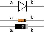
  • Digital multimeters have a special setting for testing a diode, usually labelled with the diode symbol.
  • Connect the red (+) lead to the anode and the black (-) to the cathode. The diode should conduct and the meter will display a value (usually the voltage across the diode in mV, 1000mV = 1V).
  • Reverse the connections. The diode should NOT conduct this way so the meter will display "off the scale" (usually blank except for a 1 on the left).

Testing a diode with an ANALOGUE multimeter

  • Set the analogue multimeter to a low value resistance range such as × 10.
  • It is essential to note that the polarity of analogue multimeter leads is reversed on the resistance ranges, so the black lead is positive (+) and the red lead is negative (-)! This is unfortunate, but it is due to the way the meter works.
  • Connect the black (+) lead to anode and the red (-) to the cathode. The diode should conduct and the meter will display a low resistance (the exact value is not relevant).
  • Reverse the connections. The diode should NOT conduct this way so the meter will show infinite resistance (on the left of the scale).
For further information please see the diodes page.
You may find it easier to test a diode with the simple tester project.

Testing a transistor

Transistors can be damaged by heat when soldering or by misuse in a circuit. If you suspect that a transistor may be damaged there are two easy ways to test it

Testing with a multimeter

Use a multimeter or a simple tester (battery, resistor and LED) to check each pair of leads for conduction. Set a digital multimeter to diode test and an analogue multimeter to a low resistance range

Test each pair of leads both ways (six tests in total)
  • The base-emitter (BE) junction should behave like a diode and conduct one way only
  • The base-collector (BC) junction should behave like a diode and conduct one way only
  • The collector-emitter (CE) should not conduct either way
The diagram shows how the junctions behave in an NPN transistor. The diodes are reversed in a PNP transistor but the same test procedure can be used


Testing in a simple switching circuit

Connect the transistor into the circuit shown on the right which uses the transistor as a switch. The supply voltage is not critical, anything between 5 and 12V is suitable. This circuit can be quickly built on breadboard for example. Take care to include the 10k ohm resistor in the base connection or you will destroy the transistor as you test it!

If the transistor is OK the LED should light when the switch is pressed and not light when the switch is released.
To test a PNP transistor use the same circuit but reverse the LED and the supply voltage.
Some multimeters have a 'transistor test' function which provides a known base current and measures the collector current so as to display the transistor's DC current gain hFE