 The techniques used for each type of meter are very different so they are treated separately:
 Testing a diode with a DIGITAL multimeter
- Digital multimeters have a special setting for testing a diode, usually labelled with the diode symbol.
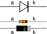
- Connect the red (+) lead to the anode and the black (-) to the cathode. The diode should conduct and the meter will display a value (usually the voltage across the diode in mV, 1000mV = 1V).
- Reverse the connections. The diode should NOT conduct this way so the meter will display "off the scale" (usually blank except for a 1 on the left).
Testing a diode with an ANALOGUE multimeter
- Set the analogue multimeter to a low value resistance range such as × 10.
- It is essential to note that the polarity of analogue multimeter leads is reversed on the resistance ranges, so the black lead is positive (+) and the red lead is negative (-)! This is unfortunate, but it is due to the way the meter works.
- Connect the black (+) lead to anode and the red (-) to the cathode. The diode should conduct and the meter will display a low resistance (the exact value is not relevant).
- Reverse the connections. The diode should NOT conduct this way so the meter will show infinite resistance (on the left of the scale).
You may find it easier to test a diode with the simple tester project.

ليست هناك تعليقات:
إرسال تعليق